
1 Civilian CAM - User instruction
1.3 Access to ancillary information
1.7 Service Request definition for Standard Products (New Acquisitions)
1.7.2 Observation time constraints
1.7.6 Specific Parameters
insertion
1.8 Service Request definition for Standard Products (Catalogue)
1.8.4 Specific Parameters
insertion
1.9.5 Estimate / Estimation Info
2.0
Service List and constraints
2.0.1 Services for the
generation of SAR standard products
2.0.2 Services for the generation of SAR high
level and speckle filtered products
1 Civilian CAM - User instruction
1.1
Prerequirements
In order to
use
- 400Mhz processor minimum
- 64 Mbyte RAM
The
following software needs to be installed on the client machine:
- Internet Browser (Javascript Enabled)
- J2SDK 1.4.2_06
A network
connection properly configured shall guarantee TCP/IP protocol between the two
machines.
1.2 Access
to CAM
The access
to the CAM Component is performed by using a client machine connected to the
In order to
access to
http://www.cosmo-skymed.
The
following images provide the UGS main home page.
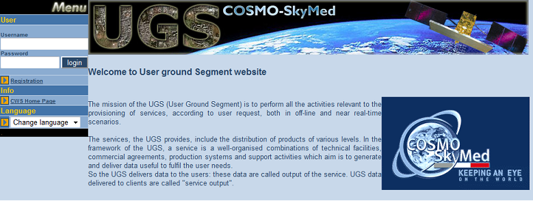
Figure 1:
Main window
The page is
mainly divided in two frames:
- The
left frame shows the menu bar
- The
central frames shows introducing information related to Cosmo-SkyMed Mission
1.3
Access to ancillary information
The
The left
menu bar provides the following links/tools organized in three groups:
· User
· Info
· Language
User contains:
· Username/Password: text box to insert login data
· Login button: allows to login to the system for
registered users
· Registration link: allows to
subm
Info contains:
· CSW Home page: such link provides access to the
Cosmo Web S
Language contains:
· Language combo box
Note that the interface is actually provided both in English, Italian
and French language. You can sw
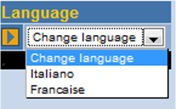
Figure 2:
Language sw
1.4
Login and Logout
The service
request defin
In the
following paragraph the procedures to login and logout into and from the system
are described.
1.4.1 Login Phase
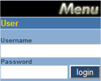
Figure 3:
Login form
In the menu
frame, into the login box, the user has to fill fields named “Username” and
“password” respectively w
In order to
complete the login procedure the user has to click on the login button.
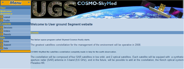
Figure 4:
Logged user main page
A new menu
is loaded w
Namely they
are:
· Log out: used to log out from the system and return to
main page as an anonymous user
· Profile: used to mon
· Services: used to subm
· Orders: used to mon
· Reports: used to service request reports.
· Home: used to return to the homepage
· Help: link to the
When a user
is logged a message on the top-left is shown w
1.4.2
Logout
It is
possible to logout at anytime.
In order to
perform the logout operation, the user clicks on “logout” menu entry on
the upper menu bar.
The UGS home
page is loaded again and the operator is on UGS home page as anonymous user.
1.4.3
Session timeout
User
session has a duration of 60 minutes after that, on any operation required the
system responds w
1.5
Profile management
The profile
parameters can be visualised and modified.
In order to
access to profile visualisation functional
The page w
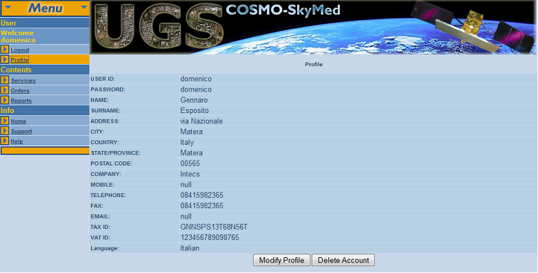
Figure 5:
User profile information
The user can decide to
modify entered parameters by pressing the “ModifyProfile”
button. A new page is loaded as shown in following image:
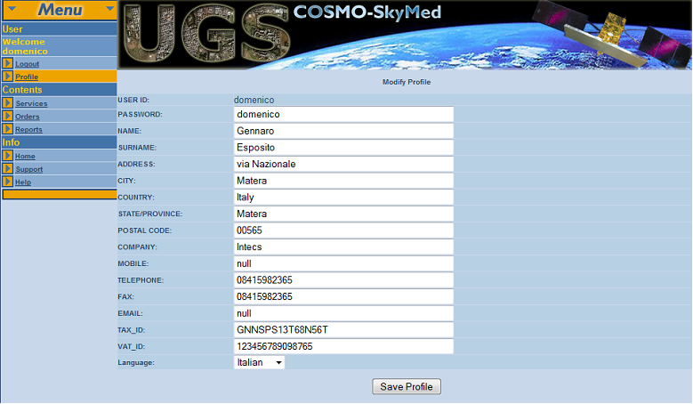
Figure 6:
Profile management window
Modified
parameters can be saved by pressing the “SaveProfile”
button.
In order to
cancel parameters modification,
1.6 Service Browsing
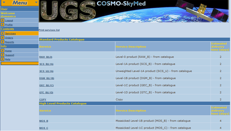
Figure 7:
Service Browsing
CAM Human
Machine Interface provides graphical tools for navigation through the available
services.
In order to
access to the available services description, the logged user clicks the button
named “services” on the left bar of the home page. A new page is loaded
into the main frame of the home page as shown in Figure 7.
The new
page contains a table w
§
Standard products: Catalogue
§
High Level Products: Catalogue
§
Standard products: New Acquis
§
High Level Products: New Acquis
For each service
of the list, a brief description and the estimated delivery time are indicated.
The
services displayed are only available to the user profile
By clicking
on the name of any Standard or High Level Product Catalogue service
a new page containing the link to define a new order for the service and a
short description is loaded.
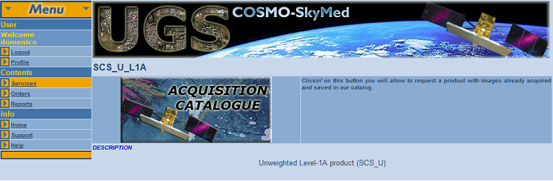
Figure 8:
Service main page
The name of
the selected service is provided on the left of the middle bar as shown in Figure 9.
![]()
Figure 9:
Service name identification
One button
is presented on the central frame
- “Acquis
Clicking
such button the user can create a new order for the selected service.
By clicking
on the name of any Standard or High Level products New Acquis
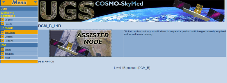
Figure 10:
Standard Products New Acquis
1.7
Service Request definit ion
for Standard Products (New Acquisit ions)
In order to
define a new service order for standard products, that foresees a new acquis
The
description of the service is shown on the main central frame; the user can now
start the service defin
This
operation opens a popup window, starting the wizard application that will guide
the user in defining the main parameters, by means of a progression of panels.
The current
step of service defin
See also section
2.0 for service request constraints.
1.7.1
Geographical area info
This step
allows the defin
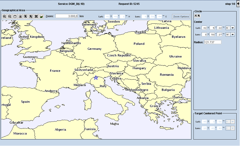
Figure 11:
Service Defin
The world map provides at first, on the top a map toolbar allows manipulation of the graphical representation. The “MAP Tool bar”: contains the following tools:
 “Zoom In”: allows zooming in
on a particular pos
“Zoom In”: allows zooming in
on a particular pos “Zoom Out”: allows zooming out on a particular pos
 “PAN”: lets you pan on the map by dragging the display in any
direction w
“PAN”: lets you pan on the map by dragging the display in any
direction w “Select w
 “Select w
 “Select w
 Target Point: tool
allows the draw of target point of the area of interest
Target Point: tool
allows the draw of target point of the area of interest  Layer control: tool allows
changing the Layer(s) Visualization.
Layer control: tool allows
changing the Layer(s) Visualization. - Crisis area: button to view on the map the
defined crisis area (this button is enable only in crisis operational mode)
 “Zoom Value”: shows the actual zoom value. It
is also possible to modify directly such value. The map is redrawn
accordingly
“Zoom Value”: shows the actual zoom value. It
is also possible to modify directly such value. The map is redrawn
accordingly - “Lat” lat
- “Long” long
Note that
the layers visualization changes according to the zoom level; in fact when the
zoom level is raised some information (e.g. toponyms)
change to visible setting.
The ![]() button, on the top side near
the step counter, allows to access to the next step of service defin
button, on the top side near
the step counter, allows to access to the next step of service defin
1.7.1.1 Polygonal area
The user
can specify a polygon as area of interest by selecting the polygon selection
tool contained in the map tool bar described in section 1.7.1 and drawing a polygon on the map (Figure 12). The
table contained in the “Polygon points” panel is updated anytime a new vertex
is added providing the corresponding coordinates.
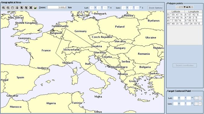
Figure 12:
Polygonal area selection
In order to
close a defined area the user can
- e
- or double-click on a point on the
map corresponding to the last vertex to be added.
In both
cases the polygon is automatically closed.
To define a
polygon, the user can also manually insert vertex coordinates into the table
contained in the panel “Polygon points”. Once the user has inserted all the
vertexes record in the table, he/she can draw the corresponding polygon on the
map by clicking the button ![]() on top of the
table “Polygon points”.
on top of the
table “Polygon points”.
The panel “Polygon points”. contains a toolbar to
manage the coordinate values, w
 Remove: Removes the selected record from the
coordinates list
Remove: Removes the selected record from the
coordinates list  Append after: Appends a record after the
selected one
Append after: Appends a record after the
selected one  Insert before: Inserts a record before the
selected one
Insert before: Inserts a record before the
selected one  Add at the top: Adds a record at the top of the
list
Add at the top: Adds a record at the top of the
list  Add at the end: Adds a record at the end of the
list
Add at the end: Adds a record at the end of the
list  Remove all: Removes all records of the list
 Show on map: Draws the polygon on the map
1.7.1.2 Circular area
The
user can specify a circle as area of interest by selecting the circle selection
tool contained in the map tool bar described in section 1.7.1 and drawing a circle on the map.
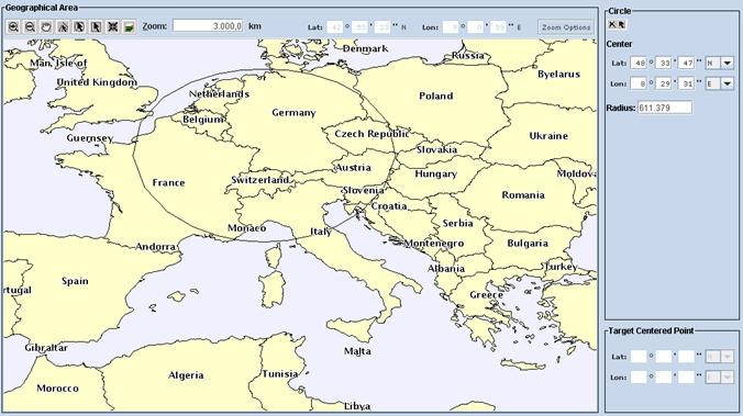
Figure 13:
Circular area selection
Circle selection
occurs selecting the centre on the map and dragging until the desired radius is
reached. While dragging the radius value (expressed in Km) is shown in the
field “Radius” in the panel “Circle” on the right of the page. Once the circle
has been defined the centre coordinates are shown in the panel “Circle”.
The
user can also specify the circle parameters (centre coordinates and radius) in
the panel “Circle” manually. Such panel contains also a tool bar holding the
following
· ![]() Clear values: Clears all the values contained in
the “Circle” panel fields
Clear values: Clears all the values contained in
the “Circle” panel fields
· ![]() Show on map: Draws on map the circle
corresponding to the centre and radius specified by the user in the panel
“Circle” fields.
Show on map: Draws on map the circle
corresponding to the centre and radius specified by the user in the panel
“Circle” fields.
1.7.1.3 Rectangular area
The
user can specify a rectangle as area of interest by selecting the rectangle selection
tool contained in the map tool bar described in section 1.7.1 and drawing a rectangle on the map.
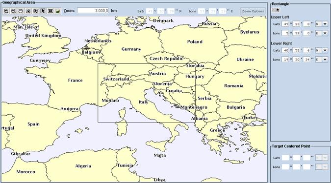
Figure 14:
Rectangular area selection
Rectangle
selection occurs selecting a vertex on the map and dragging until the desired
rectangle is reached. Once the rectangle has been defined upper left and the
lower right corner coordinates are shown in the panel “Rectangle”.
The
user can also specify the rectangle upper left and lower right corner
coordinates in the panel “Rectangle”. Such panel contains also a tool bar
holding the following
· ![]() Clear values: Clears all the values contained in
the “Rectangle” panel fields
Clear values: Clears all the values contained in
the “Rectangle” panel fields
· ![]() Show on map: Draws on map the rectangle
corresponding t upper left and lower right corner specified by the user in the
panel “Rectangle” fields.
Show on map: Draws on map the rectangle
corresponding t upper left and lower right corner specified by the user in the
panel “Rectangle” fields.
1.7.1.4 Target centered
point
Once the
user has selected the area of interest, he/she can specify the “Target centered point” by clicking on the corresponding button of
the main tool bar described in section 1.7.1. On the right of the map the panel
“Target centered point” appears and the user can
specify such a point by:
- e “Show
on map” of the panel toolbar;
- or clicking on the map.
In both
cases an asterisk corresponding to the selected point appears on the map.
The “Target
centered point” panel toolbar contains also a tool ![]() to clear the point coordinates.
to clear the point coordinates.
1.7.2
Observation time constraints
In this
step the user defines the temporal constraints of the acquis
The user can
select the type of the acquis
- “single” (for requests that
foresees single acquis
- “periodical” (for requests that
foresees regular time spaced acquis
- “repet
The user
can fill start and stop date/time of the service time w
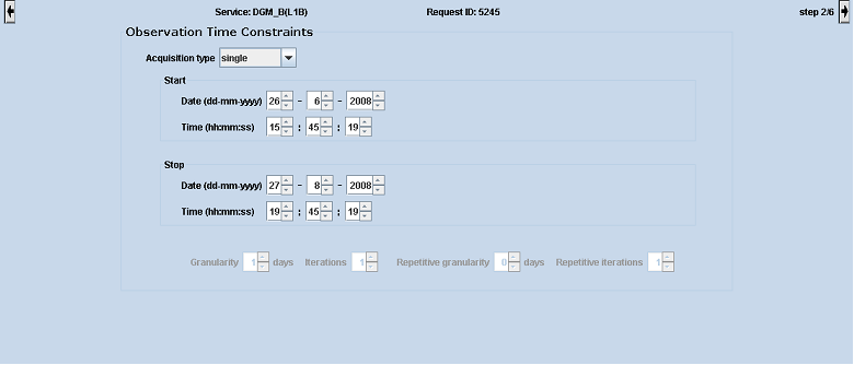
Figure 15:
Service Defin
User can also define:
- Granular
- Iterations: the number of service
requests (for periodical and repet
- Repet
- Repet
The ![]() button allows accessing the
next step of service defin
button allows accessing the
next step of service defin![]() button allows coming back to
the previous step.
button allows coming back to
the previous step.
1.7.3
Satellit e parameters
In this
step the user is allowed to define specific COSMO-SkyMed
constellation parameters and to select the acquis
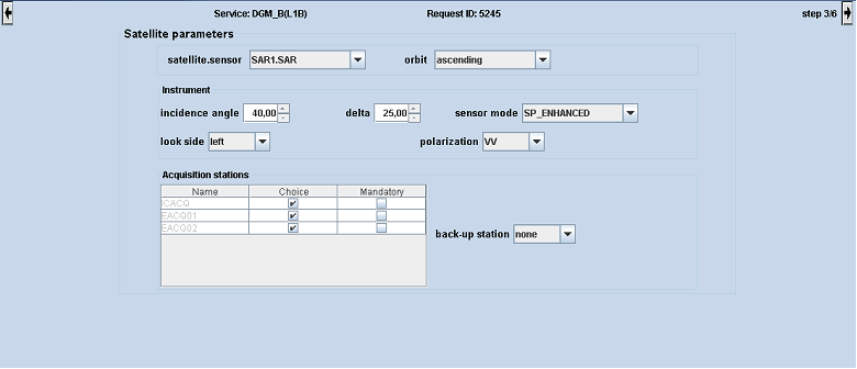
Figure 16:
Service Defin
The user
can select the satell
Note: The user
is allowed not to specify a value for satell
Further,
the user can specify SAR instrument parameters (“instrument” panel).
Specifying incidence
angle and delta values, user can force acquis
SensorMode,
Polarization and so on are well explained in paragraph 1.8.1.1.2.
Into the
Acquis
The ![]() button allows accessing the
next step of service defin
button allows accessing the
next step of service defin![]() button
allows coming back to the previous step.
button
allows coming back to the previous step.
1.7.4
Delivery Type Choice
Through the delivery type options form the user is allowed to insert the parameters related to data delivery. User can select the preferred kind of delivery:
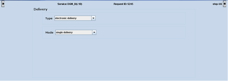
Figure 17:
Service Defin
- “electronic
delivery” (FTP delivery, next panel is “Ftp Delivery”
panel),
- “media
delivery” (Mail delivery, next panel is “Mail Delivery”
panel).
The “Mode” of
the delivery can also be selected. This field can hold the following values:
· “single” - the user requires a single
delivery of the product.The delivery mode single (single delivery for the all products) is appropriate only for request that involves few standard products;
· “in batch”- the user requires a multiple
delivery of the product.The delivery mode in batch means that each product is delivered one by one.
The ![]() button allows accessing the
next step of service defin
button allows accessing the
next step of service defin![]() button
allows coming back to the previous step.
button
allows coming back to the previous step.
1.7.5
Delivery options
1.7.5.1 FTP Delivery
Through
the FTP delivery panel the user is allowed to insert the parameters
related to data delivery by mean electronic link using FTP protocol. The
opportun
The following
parameters can be inserted by user:
· Date (if possible) for delivery wished by the user (the estimated
processing time for selected service is shown)
· the product format by means of
the related combo box. Valid values for product format are for instance (valid values
list depends on the service):
o HDF5,
o HTML,
o JPEG,
o GEOTIFF
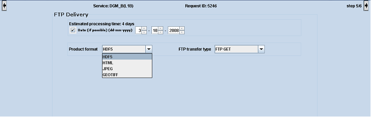
Figure 18:
Service Defin
· the FTP transfer type by means
of the last combo box
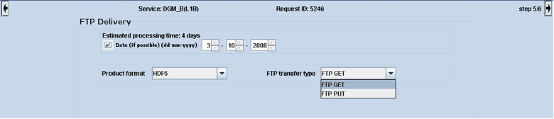
Figure 19:
Service Defin
In case the
user selects an FTP GET mode, the user will download the
generated product locally via the FTP GET protocol (see section 1.9.7 for
details).
In case the
user selects the FTP PUT mode, the following parameters shall be
inserted by user:
- IP Address of the destination server
- user
- Password
- Confirmation of the password, for secur
Please note
that more than one IP address can be provided together w
The
inserted address(es) can be
removed by checking the box on the left of the inserted record and clicking the
“Remove selected” button.
Clicking “Select
All” button, all the check boxes at the left of inserted ftp accounts will
be selected allowing removing the accounts all at once.
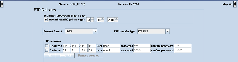
Figure 20:
Service Defin
The ![]() button allows accessing the
next step of service defin
button allows accessing the
next step of service defin![]() button
allows coming back to the previous step.
button
allows coming back to the previous step.
1.7.5.2 Media Delivery
In case the
user selects the media delivery option the
following parameters shall be filled:
- Date (if possible) for delivery
wished by the
user (the estimated processing time for selected service is shown)
- Via: the carrier of the data (DHL)
- the product format by mean
of the related combo box. Valid values for product format are for instance
(valid values list depends on the service):
- HDF5
- HTML
- JPEG
- GEOTIFF
- Medium required (CDROM, DVDROM, EXABYTE,
and TAPE). The kind of media is correlated to the selected product format
so that for example is not possible to select an EXABYTE support in case
of HTML product format
To add a
new mail address, the user shall click on “ADD” button. A form will be
displayed on the screen, that shall be filled by the user (fields w
After
filling the mail address fields, the user clicks on “OK” button to
confirm the form data or “close” to abort the operation.
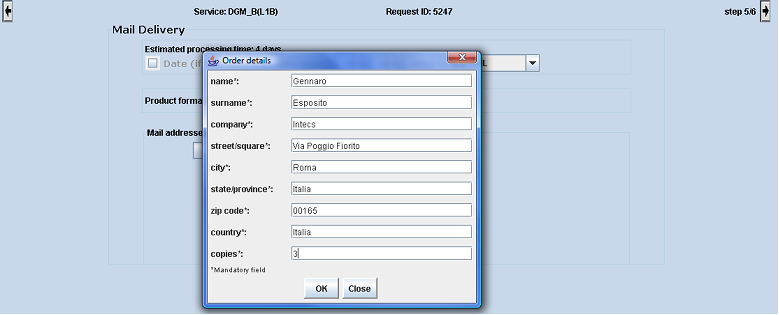
Figure 21:
Service Defin
After
inserting mail addresses where products shall be delivered, the screen will
appear as following figure:
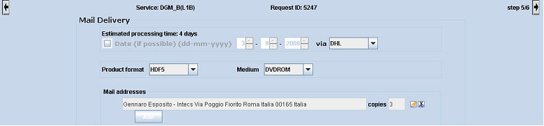
Figure 22:
Service Defin
The ![]() “Remove” tool on the
right of the form allows removing the related mail address from the list, while
“Remove” tool on the
right of the form allows removing the related mail address from the list, while
![]() the “Ed
the “Ed
The ![]() button allows accessing the
next step of service defin
button allows accessing the
next step of service defin![]() button
allows coming back to the previous step.
button
allows coming back to the previous step.
1.7.6
Specific Parameters insertion
Note: this
page will be visualized if needed to define a service request on the selected
service.
This page
allows the insertion of specific parameters defined in according to the kind of
service. The page provides the several sections each of them containing the
parameter name, a parameter description and the control used to subm
Note that
when a request is saved,
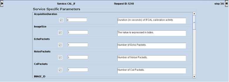
Figure 23:
Service Defin
The ![]() button allows accessing the
next step of service defin
button allows accessing the
next step of service defin![]() button
allows coming back to the previous step.
button
allows coming back to the previous step.
1.7.7
Payment Methods
Note: this
page is not foreseen for all users.
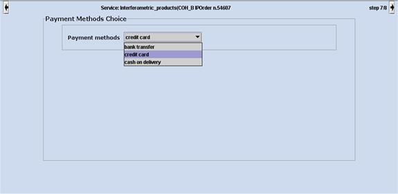
Figure 24:
Service Defin
Commercial users can specify the payment method for the defined service, selecting a value from the combo box of this form. Payment methods can assume one of these three values:
- Bank transfer
- Cred
- Cash on delivery
The ![]() button allows accessing the
next step of service defin
button allows accessing the
next step of service defin![]() button
allows coming back to the previous step.
button
allows coming back to the previous step.
1.7.8 Order details
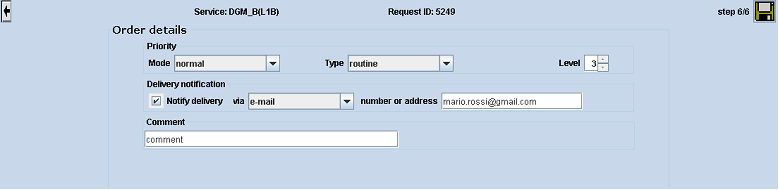
Figure 25:
Service Defin
The last
page allows the user the insertion of Prior
· Mode: the operative mode. It can assume the following
values (depending on the user profile):
- “routine”,
- “crisis”,
-
“very urgent”.
The values of
this field are in accord w
· Type: type of the request. It can take on the
following valid values (depending of user profile):
- “routine”,
-
“privileged”.
· Level: A prior
· Notify Delivery: The request notification state via
e-mail, telephone or fax according to
· Comment: A short description to be saved together w
The ![]() button allows saving the current service
request; the
button allows saving the current service
request; the ![]() button
allows coming back to the previous step.
button
allows coming back to the previous step.
When the
user clicks on the ![]() button, a confirmation message is
shown. The only button provided allows closing the main window.
button, a confirmation message is
shown. The only button provided allows closing the main window.
Figure 26:
Confirmation window
Note when a
request is saved,
1.8
Service Request definit ion for Standard Products
(Catalogue)
In order to
define a new service order for catalog standard
products, the logged user selects the “services” menu
The
description of the service is shown on the main central frame; the user can now
start the service defin
This
operation changes the content of the central frame starting the wizard
application that will guide the user in defining the main parameters.
See also
section 2.0 for service request constraints.
1.8.1
Catalogue Browser
In order to
define a new service order for catalogue products, the logged user selects the “services”
menu
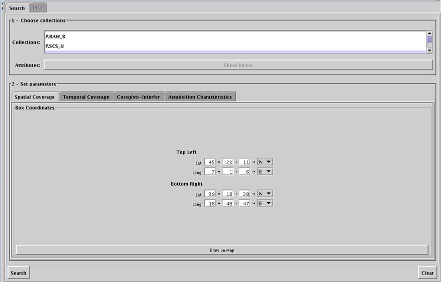
Figure 27:
Catalogue service list
Note that copy
service allows to retrieve an already processed and catalogued product (raw or
higher level) among the available collections .
The
description of a generic service is shown on the main central frame; the user
can now start the service defin
Figure 28:
Acquis
This
operation changes the content of the central frame starting the application
that will guide the user in defining the main parameters.
1.8.1.1 The Catalogue
Browser
The operator can do the Historical Acquis
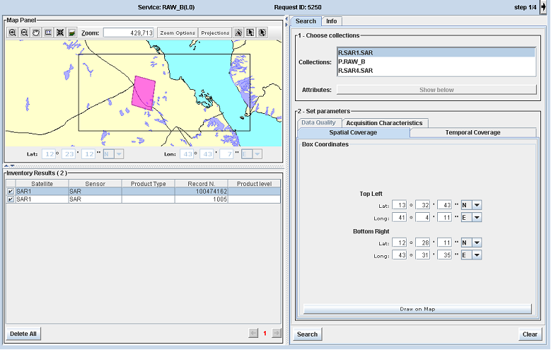
Figure 29:
Catalogue Browser window
Five parts compose this window:
- Map Viewer
- Search panel
- Inventory Results table
- Information panel
- Buttons tool bar
1.8.1.1.1 Map Viewer
For the map tool description see the paragraph 1.7.1.
1.8.1.1.2 Search panel
The Search
panel provides sections to compose a complex catalogue query.
Figure 30:
Search panel
To compose a query:
·
select one
collection from the list named Collections.
The allowed collections for the logged user listed in the panel
are loaded at run time. Possible collections are the following:
o R.SARn.SAR: collection of raw data, where n identifies the order
number of satell
o P.RAW_B: collection of raw data product s(L0)
o P.SCS_B and P.SCS_U: collection of single look complex products (L1A)
o P.DGM_B: collection of detected, multilooked
and ground projected products (L1B)
o P.GEC_B: collection of ground projected and ellipsoid corrected
products (L1C)
o P.GTC_B: collection of ground projected and terrain corrected
products (L1D)
o P.MOS_B: collection of mosaicked
products (from L1B)
o P.MOS_C: collection of mosaicked
products (from L1C)
o P.MOS_D: collection of mosaicked
products (from L1D)
o P.MOS_H: collection of mosaicked
products (from auxiliary DEM or DEM produced via L1A)
o P.CRG_A: collection of coregistered
products (from L1A)
o P.CRG_B: collection of coregistered
products (from L1B)
o P.PBR_B: collection of band reduction product
o P.SPF_B: collection of speckle filtered products (from L1B)
The collections
displayed in the search panel depend on the service request chosen.
P is for product, R for raw.
·
click on the Show below
button to obtain the searchable collection query attributes
·
set the
parameters in the different enabled panels (panels enabled depend on the choice
of collection):
§ Temporal Coverage:
this panel allows the user to set the start and stop date and time only if the Time
Range check button is enabled. All times are expressed in UTC time.
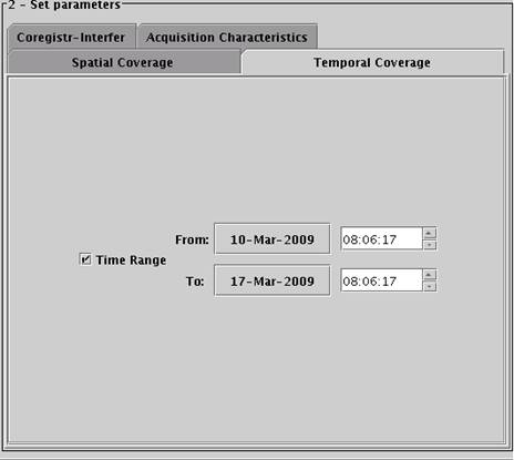
Figure 32:
Temporal Coverage panel
By default Time
Range check button is enabled and temporal coverage is null.
§ Acquis
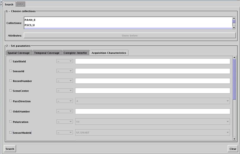
Figure 33:
Acquis
The Acquis
|
Attribute |
Description |
Operation |
On Collections |
|
Satell |
Satell |
= |
R
& P |
|
SensorId |
Sensor Identifier |
= |
R & P |
|
ProductType |
Product Typology |
= |
P |
|
RecordNumber |
Numeric
unique identifier for a product |
= |
R & P |
|
ProviderId |
Unique
identifier of the Provider |
|
R & P |
|
OriginatorCollection |
List
of Collection Identifiers from which product has been processed |
|
R & P |
|
ProductFilename |
File
name |
= |
R & P |
|
Spatial Coverage |
Spatial
Coverage of a single |
|
R & P |
|
-
Box |
Upper left corner, Lower Right Corner of the rectangular shape in term
of Long |
= |
R & P |
|
-
Polygon |
List of vertex (last point coinciding w |
= |
R & P |
|
-
Circle |
Centre
in term of Long |
= |
R & P |
|
Temporal Coverage |
Temporal
Coverage (Start&End Time) of a single |
|
R & P |
|
- StartOfCoverage |
Start
Date/Time of the |
= |
R & P |
|
- EndOfCoverage |
End
Date/Time of the |
= |
R & P |
|
SceneCentre |
Scene
Centre Coordinates. Scene
Centre Coordinates (defined as couple Lon, Lat that is FLOAT(5,2)
: FLOAT(4,2) with ranges -180:180 and –90 : 90 respectively. For example, 16.60:40.67.) |
= |
R
& P |
|
PassEquatorXLong |
Nadir
Equator Crossing Long |
|
R |
|
PassDirection |
Flight
direction of the Satell |
= |
R & P |
|
VerticalCoverage |
Vertical
coverage (min and max height) |
|
R & P |
|
-
MinimumHeight |
Minimum
satell |
|
R & P |
|
-
MaximumHeight |
Maximum
satell |
|
R & P |
|
Orb |
Absolute Orb |
= |
R & P |
|
Track |
WRS
Track Number (Not used for COSMO missions) |
|
R |
|
Frame |
WRS
Frame Number (Not used for COSMO mission) |
|
R |
|
MissionPhaseId |
Indication of the mission phase |
|
R & P |
|
Band |
Identifier
of a Sensor Band |
|
R & P |
|
ViewAngle |
View
(opening) angle of the sensor. |
= |
P |
|
Polarization |
Polarization (Transm |
= |
R & P |
|
SensorModeId |
Specific sensor mode |
= |
R & P |
|
SensorModeDescription |
Descriptive text of specific sensor mode |
|
R & P |
|
Gain |
Gain Value |
|
R |
|
Illumination |
Sun azimut and elevation |
|
R |
|
-
SunAzimut |
Sun Azimut |
|
R |
|
-
Sun Elevation |
Sun Elevation |
|
R |
|
CloudCoverage |
Percentage of
coverage: clouds |
= |
R & P |
|
Acquis |
Acquis |
= |
R & P |
|
CorrectionParameters |
Delta (errors) angles to nominal sensor pointing direction |
|
R & P |
|
-
DeltaSideWardLookingAngle |
Nominal look angle of the full observed swath (unsigned angle between
nominal reference direction of the multi-beam and satell |
= |
R & P |
|
"-
DeltaForwardLookingAngle" |
Delta w |
|
R & P |
|
-
DeltaRoll |
Delta rotation to nominal satell |
|
R & P |
|
-
DeltaP |
Delta rotation to nominal satell |
|
R & P |
|
DeltaYaw |
Delta rotation to nominal satell |
|
R & P |
|
AtmosphericCond |
Atmospheric parameters useful for special applications |
|
R |
|
- LocalPrecip |
local precip |
|
R
& P |
|
- MeanWaterVapour |
mean water vapour |
|
R & P |
|
-
IonosphereTotalElectronCount |
Ionospheric Total Electron Content |
|
R & P |
|
IncidenceAngle |
Near and Far incidence angle |
|
R & P |
|
-
NearRangeIncidenceAngle |
Near incidence angle |
= |
R & P |
|
-
FarRangeIncidenceAngle |
Far incidence angle |
= |
R & P |
|
ProcessingInformation |
Processing algor |
|
P |
|
- ProcessingAlgor |
Processing algor |
|
P |
|
- ProcessingCentre |
Processing centre |
|
P |
|
- ProcessingDate&Time |
Processing date-time |
|
P |
|
- ProcessingType |
Processing type |
|
P |
|
AncillaryData |
Short
description about ancillary data used in processing algor |
|
P |
|
AuxiliaryData |
Short
description about auxiliary data used in processing algor |
|
P |
|
OtherSpecificData |
Specific
Data different from collection to collection or for future use; they are
dynamically defined into the Database in the form TAG – Value. |
|
R & P |
|
Thumbnail |
Thumbnail
of the raw data |
|
R & P |
|
QuickLookId |
Quick
Look identifier of the raw data |
|
R & P |
|
BandReductionFlag |
Band Reduction flag. |
= |
R & P |
|
LookSide |
Look
side. |
= |
R & P |
|
DeliveryMode |
Identification
of the processing mode used to meet the delivery time constraints. |
= |
P |
|
MissingLinesPercentage |
Missing Lines
percentage |
= |
R |
|
NumberOfGaps |
Number of
Gaps |
|
R |
|
Resolution |
Spatial resolution value |
= |
R & P |
|
LinkedCoregisteredData |
Lists of record numbers of data coregistered
w
|
N.A. |
P |
|
TandemInterfCouple |
List of record numbers of couple of data that are in CSK tandem interferometric configuration. 8) data must have the same look side It would be also suggestable to identify the
master in the couple (info needed for interferometric
processing). The master is the one whose sensing start time is before |
N.A. |
R & P |
|
MasterRecordNumber |
List
of record numbers of the master image among the linked coregistered
data or between the inferometric couple (see above). |
N.A. |
P |
|
LinkedRepeatedTrackInterf |
List of record numbers of data that could be used for interferometry purposes (repeated tracks) w
|
N.A. |
R & P |
Table 1:
Acquis
Please,
remind that most controls have tool-tips explaining the meaning of data shown inside..
§ Spatial Coverage: this
panel allows the user:
o to define the rectangle coordinates for catalogue data searching (see rectangle
map tool)
o to visualize the coordinates of the geographical area of interest for:
§ bounding box (see Auto map tool)
§ vertexes polygon (see Polygon map tool)
§ circle (see Radius map tool)
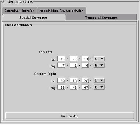
Figure 34:
Spatial Coverage panel (e. g. bounding box coverage)
§ Coregistr-Interfer: this panel (enabled
only for R collections) allows the user to define how interferometric
image couple shall be acquired:
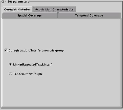
Figure 35:
Coregistr-Interfer panel
§ The Search
button: to subm
§ The Clear
button: to clear all the parameters text fields.
1.8.1.1.3 Inventory
Results
The Inventory
Results panel displays the acquis
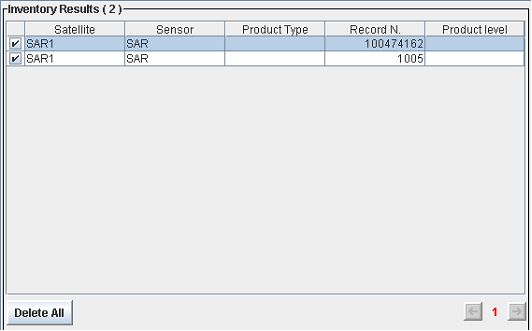
Figure 36:
Inventory Results panel
Each record
is also represented on the map.
Selecting a
row, is possible to display information simply selecting the folder tab “Info”
on the right side of the screen.
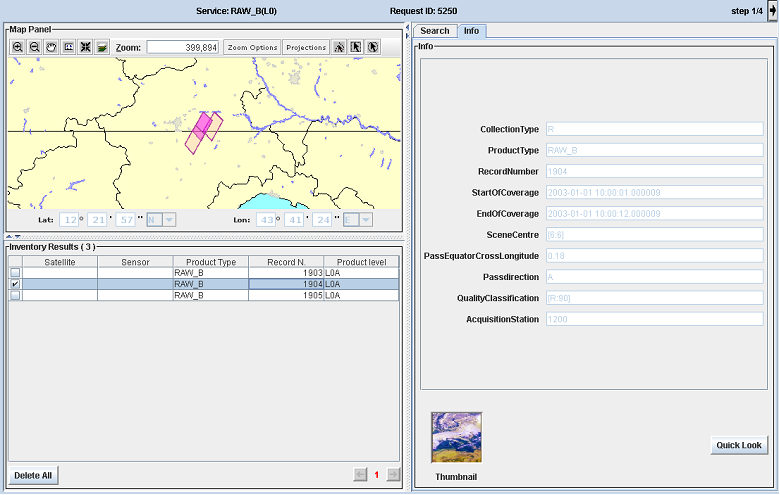
Figure 37:
Service Defin
The
following parameters will be displayed:
- Collection Type
- Product Type
- Record Number
- Start of coverage
- End of coverage
- Scene centre
- Pass
equator cross long
- Pass direction
- Qual
- Acquis
The meaning
of them is explained in the previous paragraph.
The table columns are sortable:
one click on the column header to obtain ascending sort, second click to obtain
descending sort and another click to come to the beginning s
The
·
in a bold colour the areas selected;
·
in a sem
·
all the remaining areas are not displayed.
In order to select the product retrieved, click on the
check column. One or more products can be selected.
1.8.1.1.4 Information
Panel
The Information
panel provides information for the specified Historical Acquis
The Information
panel is enabled only when the user selects an
Historical Acquis
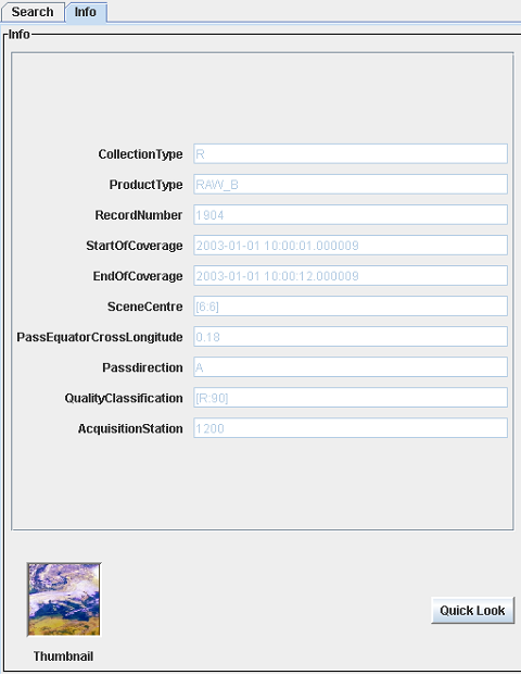
Figure 38:
Information panel
Below
there are some of the most general returned for the two different catalogue type:
CollectionType: type of the
collection;
ProductType: product typology;
RecordNumber: numeric unique
identifier;
StartOfCoverage: start date/time of the
EndOfCoverage: end date/time of the
SceneCentre: scene centre
coordinates;
PassEquatorCrossLong
Passdirection: flight direction of
the satell
Qual
Acquis
Other Button:
Thumbnail: the thumbnail image returned
Quicklook
button: the button opens the quick look image in a different dialog (see below).
If the current Historical Acquis
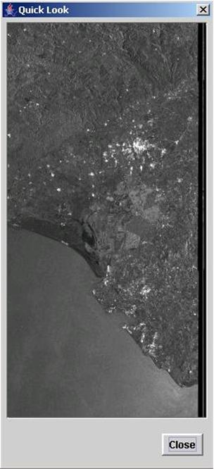
Figure 39:
Quicklook dialog
1.8.1.2 Compose and submit catalogue research query
As described in Search
panel section, the user could create a complex query.
In order to compose a complex query:
·
click on Search panel, if not selected;
·
choose the
collection type from the Collection
list;
·
click on
the Show Below button
·
fill the
enabled parameters text fields;
·
define the
spatial coverage;
·
click on
the Search button in
the bottom panel.
1.8.1.3 Choose Inventory
Catalogue from the result set
Warning: If the selected product is not a standard frame and the AOI is smaller than product area covered, the System doesn t provide the product basing on the AOI but it provides the full product coverage as standard product size. In this case the delivery mode single is not appropriate.
After the
As
described before, the

Figure 40:
Catalogue Browser dialog
To complete
the order, the user clicks on the check box in order to select the record
desired and clicks on the button “Next” placed at the top right of the
wizard.
1.8.2
Delivery Type Choice
Please
see the paragraph 1.7.4.
1.8.3
Delivery options
Please
see the paragraph 1.7.5.
1.8.4
Specific Parameters insertion
Please
see the paragraph 1.7.6.
1.8.5
Payment Methods
Please
see the paragraph 1.7.6.
1.8.6
Order details
Please
see the paragraph 1.7.8.
1.9 Service
Orders management
The
“Orders” link allows the user to browse the orders saved into the order basket.
Note: The
user can manage only his service requests.
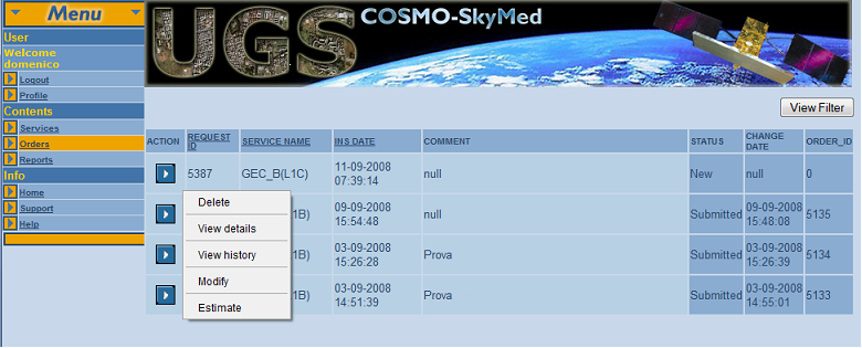
Figure 41:
Orders list
The table showed in the main frame, provide the
order list w
- “ACTION”:
clicking w
- “REQUEST
ID”: the unique identifier of the request into the order basket
- “SERVICE
NAME”: the name of the service relative the order
- “INS
DATE”: date of the order
- “COMMENT”: description of the order
- “STATUS”: order status
- “CHANGE
DATE”: date of the change order status
- ”ORDER
ID”: unique identifier of the order into the UGS system
Clicking on “REQUEST ID”, “SERVICE NAME” and “INS DATE” table t
Clicking on
![]() (action button) a pop-up menu
will be displayed.
(action button) a pop-up menu
will be displayed.
In the
following, a description of each pop-up menu entry will be given.
1.9.1
Delete
The “Delete”
entry allows the user to permanently delete a previously saved request. A
confirmation is required to perform such operation. In case such confirmation
is provided the order is no more visible on the list.
This action
is allowed in the following service request status: New, Cancelled.
1.9.2
View Details
The “View
details” entry is accessible in every request status and allows visualizing
the full set of parameters of the introduced request.
Details are
provided shown on a scrollable tabular representation.
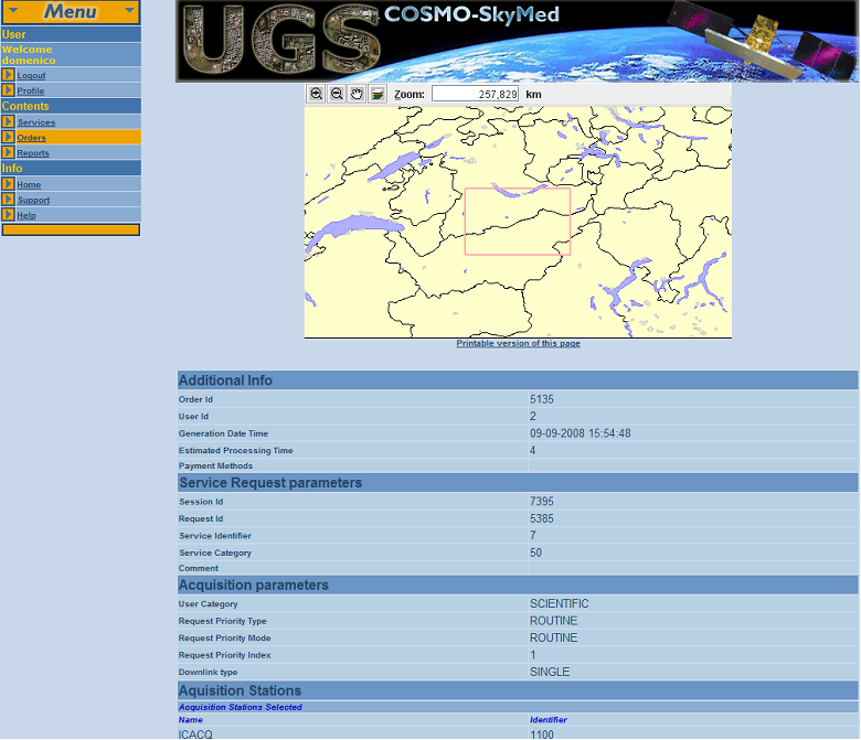
Figure 42:
View Details Window
1.9.3
Modify
The “Modify”
entry allows modifying some parameters of a previously saved request. The wizard
used to create the service request is presented again but some fields are
already filled w
Such field,
together w
The steps
are followed as in case of new request insertion. For details see section 1.7.
This action
is allowed in the following service request status: New, Cancelled.
1.9.4
Cancel
The “Cancel”
entry allows to cancel the previous estimation and to move to the “cancelled”
status so that the request can be modified and sent for estimation again or can
be defin
This action
is allowed in the following service request status: New, Cancelled.
1.9.5
Estimate / Estimation Info
The “Estimate”
and “Estimation Info” allows to show a window w
Note that a
request needs to be always estimated at least one time before
It is
possible to recall the estimation info every time that the order window is
loaded through the “estimation info” menu entry (see Figure 39).
Figure 43:
Order Estimation
The
Estimate action is allowed in the following service request status: New.
The
Estimate Info action is allow in the following service request status:
Estimated, Subm
1.9.6 Submit
The “Subm
This action
is allowed in the following service request status: Estimated.
1.9.7
Download
The “Download”
entry allows downloading the product from the UGS s
This action
is allowed in the following service request status: Available.
2.0
Service List and constraints
As
described in the section 1.6 Cosmo-SkyMed makes
available catalogue service and new acquis
In the following
we provide some remarks and constraints for the generation of SAR standard and
high level products. Another service not available for commercial user is the
Calibration service.
2.0.1
Services
for the generation of SAR standard products
REMARK
1: When the
sensor mode is set to SP_ENHANCED,
· If the user requires by
· If the user requires by
· If the user requires by
|
Service name |
Remark on the delivered service |
Constraints on sensor mode |
Constraints on beam ID (i.e. look angle) |
Constraints on polarization |
|
RAW_B (L0) |
None |
For new acquis |
For new acquis |
For new acquis |
|
SCS_B (L1A) |
If the sensor mode is SP_ENHANCED and the Band Reduction flag is
raised the delivered product is not the end point: |
For new acquis |
For new acquis |
For new acquis |
|
SCS_U (L1A) |
If the sensor mode is SP_ENHANCED and the Band Reduction flag is
raised the delivered product is not the end point: |
For new acquis |
For new acquis |
For new acquis |
|
DGM_B (L1B) |
None |
For new acquis Only imaging sensor modes are allowed, i.e: |
For new acquis |
For new acquis |
|
GEC_B (L1C) |
None |
For new acquis |
For new acquis According to the selected sensor mode, the choice of the incidence
angle is constrained. |
For new acquis |
|
GTC_B (L1D) |
None |
For new acquis |
For new acquis According to the selected sensor mode, the choice of the incidence
angle is constrained. |
For new acquis |
Table 3: SAR standard products services and related constraints
2.0.2
Services for the generation of SAR high level
and speckle filtered products
For what
concerns the sensor mode, apart from most of the calibration service requests
(last 4 rows of the following table), only imaging
sensor modes can be selected.
REMARK
1: if the
sensor mode of products to be generated is STR_PINGPONG and there is any
constraint, in order to perform a service, on the sensor mode or on the
polarization, this constraint has to be considered applicable only to one layer
of the PingPong product.
REMARK 2:
All the services that deal w
· CRG_A from Level-1A (SCS_B product)
· CRG_A from Level-1A (SCS_U product)
·
CRG_B
·
MOS_B from CRG
cannot
start from new acquis
As a
consequence, if the user wants to get coregistered
products from data to be acquired, he/she has to perform the following service
requests:
1)
services where the new acquis
2)
service where coregistration
is required (at least L0F data relative to the previous orders are in the catalogue
and their Quick Look images are available).
REMARK
3: for what
concerns the PBR_B service,
|
Service name |
Constraints on cardinal |
Constraints on sensor mode |
Constraints on beam ID/look side |
Constraints on polarization |
Other constraints |
|
MOS_B |
Minimum number: 2 (not
necessarily spatially overlapped) |
• If sensor mode is
STR_PINGPONG (PingPong),
only products w |
None |
All input products must have
the same polarization |
• All the input data must be
relative to the same UTM zone |
|
MOS_C |
Minimum number: 2 (not
necessarily spatially overlapped) |
• If sensor mode is
STR_PINGPONG (PingPong),
only products w |
None |
All input products must have
the same polarization |
• All the input data must be
relative to the same UTM zone |
|
MOS_D |
Minimum number: 2 (not
necessarily spatially overlapped) |
• If sensor mode is STR_PINGPONG (PingPong), only
products w |
None |
All input products must have
the same polarization |
• All the input data must be
relative to the same UTM zone |
|
CRG_A from Level-1A SCS_B |
Minimum number: 2 |
• Only products w |
• If sensor mode SP_ENHANCED, STR_HIMAGE, STR_PINGPONG: only products w |
All input products must have
the same polarization |
• Inputs can be extracted only
from the catalogue (i.e. the service cannot be started from new acquis • Please, note that 1.
Choose SCS_U (SCS_B) service from Catalogue 2.
Using filter options, find the first Raw datum you
need to co-register and subm 3.
Repeat the previous step for the second Raw datum. 5.
Wa 6.
Choose CRG_A service from catalogue you need, choose
P.SCS_U (P.SCS_B) collection and find the products generated in the step 4 7.
Subm |
|
CRG_A from Level-1A SCS_U |
Minimum number: 2 |
• Only products w |
• If sensor mode SP_ENHANCED, STR_HIMAGE, STR_PINGPONG: only products w |
All input products must have
the same polarization |
• Inputs can be extracted
only from the catalogue (i.e. the service cannot be started from new acquis • Please, note that 1.
Choose SCS_U (SCS_B) service from Catalogue 2.
Using filter options, find the first Raw datum you
need to co-register and subm 3.
Repeat the previous step for the second Raw datum. 4.
The system will generate some SCS_U (SCS_B) products
using the first datum and the same number of products using the second raw
datum 5.
Wa 6.
Choose CRG_A service from catalogue you need, choose
P.SCS_U (P.SCS_B) collection and find the products generated in the step 4 7.
Subm |
|
CRG_B |
Minimum number: 2 |
Only products w |
None |
All input products must have
the same polarization |
• Inputs can be extracted
only from the catalogue (i.e. the service cannot be started from new acquis |
|
MOS_B from CRG |
Minimum number: 2 |
Only products w |
None |
All input products must have
the same polarization |
• Inputs can be extracted
from the catalogue (i.e. the service cannot be started from new acquis |
|
MOS_H |
Minimum number: 2 (not necessarily
spatially overlapped) |
None |
None |
None |
• The only allowed input
collection (from catalogue) is DEM_H |
|
SPF_B |
None |
None |
None |
None |
None |
Table 4: SAR high level and speckle
filtered services and related constraints
In the
following tables are described the geographical and size contraints:
|
Acquis |
Scene coverage (Km2) |
File size (Mbytes) |
|
Enhanced Spotlight |
20 x 20 |
» 3200 |
|
Himage |
300 x 300 |
» 28800 |
|
PingPong |
300 x 300 |
» 3600 |
|
WideRegion |
300 x 300 |
» 800 |
|
HugeRegion |
400 x 400 |
» 128 |
Table 5: MOS_B, MOS_C, MOS_D geographical and size
constraints (special case)
|
Acquis |
Scene coverage (Km2) |
File size (Mbytes) |
|
Enhanced Spotlight |
20 x 20 |
» 355 |
|
Himage |
300 x 300 |
» 6200 |
|
WideRegion |
300 x 300 |
» 800 |
|
HugeRegion |
400 x 400 |
» 128 |
Table 6:
MOS_H geographical and size constraints (special case)